Measurable effects of a balun and a ground strap
Ideally, every antenna should have every critical component in place and be tuned perfectly to the frequency you’re operating on. Obviously, however, that’s far removed from “real life”. Most people end up starting with simple antennas and slowly improving them as time marches on.
I’ve certainly taken this track and have been slowing improving my favorite antenna: the Copper “Cactus” J-Pole. This antenna, which is mounted on my roof, performs quite well and was fun to build. But… I never added some critical components: a ground strap for lightening protection and a choke balun. Recently, I finally got around to adding those two missing components.
Rather than do them both at once, I decided to “do the right thing” and add them one at a time so I could measure the differences before and after the addition of each feature to see the effect it had on the antenna’s performance.
The Ground Strap
Everything I’ve read about J-Poles (and super-J-poles, which is really what mine is) says you can ground the base of the antenna directly to a ground rod. So I did just that: using a long length of very-heavy braided wire, I ran a wire from the base of the mounting pipe on the bottom of the antenna down to a ground rod.
The Choke Balun
My choke balun is simply a loop of coax placed right at the feed point of the antenna. A recent QST article showed that it’s actually pretty important to keep the coils parallel to each other when you’re creating them for the VHF and above frequencies. I attempted to do this, but I didn’t do it by wrapping the coax around a hard object. Instead I just taped the coils together, taping them inline one at a time to prevent them from crossing over each other. Which, um, mostly worked. One of these days I may reconstruct it by properly wrapping it around a segment of PVC pipe, which is typically recommended by most people.
The Results
While doing this work, I hooked up an antenna analyzer to the antenna. i did this in the shack, not directly at the base, because that’s where the radio will be connected. I’m worried about things as the radio sees it, not from the birds vantage point that rest on the antenna.
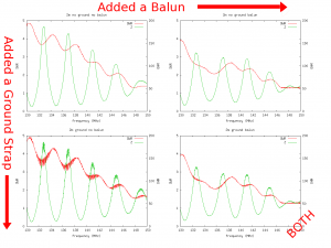
The following “quad-graph” shows the unmodified antenna in the upper left, and the completed antenna in the lower right (with the balun and ground strap connected). The other two corners show the effect of just a single feature in place.
Conclusions
The addition of both features resulted in some interesting changes in the graphs.
Adding the ground strap
Adding the ground strap did very odd things to the antenna performance. I actually used it connected for a few months before I got ahold of an analyzer to figure out what was going on. When I finally looked at the graph (bottom left) I was truly shocked. There was a very very odd sinusoidal pattern to the SWR measurement that was super-imposed over the bigger SWR pattern. If your radio signal looked like that, you’d immediately be reaching for a box of electronic parts to build a filter with. But remember, this is an SWR graph! It was this graph that finally spurred me into adding a balun in hopes it would help.
Adding the Balun
Before the addition of the balun, the antenna worked quite well for the upper part of the 2m band with a SWR near 1.5 or so, and the |Z| impedance hovering above and below 50 ohms where it should be. But things looked a little bit worse near the bottom of the 2m band (IE, below 146MHz, where the SWR went up above 2:1 and the |Z| impedance swung more wildly.)
After adding the balun, the SWR flattened out a bit and the |Z| measurement became a bit more stable as well. It’s now below 2:1 throughout the entire 2m band, which is certainly an improvement.
Adding them both together
The good news is that with both the ground strap and the balun in place, things looked better. The SWR remained flat as it had with just the balun, and the ground strap still provided its lighting protection. But the weird extra noise added to the graphs by the ground line still remained. Although, it appears the balun did significantly reduce them.
Unfortunately, the graph with the balun but without the strap looks the best, unfortunately. But I think I’ll leave the ground line connected for obvious reasons (even though I *don’t* live in a high lightning-area).
If anyone can explain to me the oddness of the spiky graph added by the ground line, I’d love to hear a good explanation. I will take the analyzer up to the roof at some point to see if it’s related to the feed line (made of about 100ft of LMR-400). One of these days.

