Measurable effects of a balun and a ground strap

Ideally, every antenna should have every critical component in place and be tuned perfectly to the frequency you’re operating on. Obviously, however, that’s far removed from “real life”. Most people end up starting with simple antennas and slowly improving them as time marches on.

I’ve certainly taken this track and have been slowing improving my favorite antenna: the Copper “Cactus” J-Pole. This antenna, which is mounted on my roof, performs quite well and was fun to build. But… I never added some critical components: a ground strap for lightening protection and a choke balun. Recently, I finally got around to adding those two missing components.

Rather than do them both at once, I decided to “do the right thing” and add them one at a time so I could measure the differences before and after the addition of each feature to see the effect it had on the antenna’s performance.

The Ground Strap

Everything I’ve read about J-Poles (and super-J-poles, which is really what mine is) says you can ground the base of the antenna directly to a ground rod. So I did just that: using a long length of very-heavy braided wire, I ran a wire from the base of the mounting pipe on the bottom of the antenna down to a ground rod.

The Choke Balun

My choke balun is simply a loop of coax placed right at the feed point of the antenna. A recent QST article showed that it’s actually pretty important to keep the coils parallel to each other when you’re creating them for the VHF and above frequencies. I attempted to do this, but I didn’t do it by wrapping the coax around a hard object. Instead I just taped the coils together, taping them inline one at a time to prevent them from crossing over each other. Which, um, mostly worked. One of these days I may reconstruct it by properly wrapping it around a segment of PVC pipe, which is typically recommended by most people.

The Results

While doing this work, I hooked up an antenna analyzer to the antenna. i did this in the shack, not directly at the base, because that’s where the radio will be connected. I’m worried about things as the radio sees it, not from the birds vantage point that rest on the antenna.

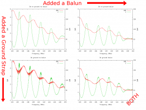
The following “quad-graph” shows the unmodified antenna in the upper left, and the completed antenna in the lower right (with the balun and ground strap connected). The other two corners show the effect of just a single feature in place.

Four graphs showing the antenna analysis

The results of the 4x analysis

Conclusions

The addition of both features resulted in some interesting changes in the graphs.

Adding the ground strap

Adding the ground strap did very odd things to the antenna performance. I actually used it connected for a few months before I got ahold of an analyzer to figure out what was going on. When I finally looked at the graph (bottom left) I was truly shocked. There was a very very odd sinusoidal pattern to the SWR measurement that was super-imposed over the bigger SWR pattern. If your radio signal looked like that, you’d immediately be reaching for a box of electronic parts to build a filter with. But remember, this is an SWR graph! It was this graph that finally spurred me into adding a balun in hopes it would help.

Adding the Balun

Before the addition of the balun, the antenna worked quite well for the upper part of the 2m band with a SWR near 1.5 or so, and the |Z| impedance hovering above and below 50 ohms where it should be. But things looked a little bit worse near the bottom of the 2m band (IE, below 146MHz, where the SWR went up above 2:1 and the |Z| impedance swung more wildly.)

After adding the balun, the SWR flattened out a bit and the |Z| measurement became a bit more stable as well. It’s now below 2:1 throughout the entire 2m band, which is certainly an improvement.

Adding them both together

The good news is that with both the ground strap and the balun in place, things looked better. The SWR remained flat as it had with just the balun, and the ground strap still provided its lighting protection. But the weird extra noise added to the graphs by the ground line still remained. Although, it appears the balun did significantly reduce them.

Unfortunately, the graph with the balun but without the strap looks the best, unfortunately. But I think I’ll leave the ground line connected for obvious reasons (even though I *don’t* live in a high lightning-area).

If anyone can explain to me the oddness of the spiky graph added by the ground line, I’d love to hear a good explanation. I will take the analyzer up to the roof at some point to see if it’s related to the feed line (made of about 100ft of LMR-400). One of these days.

Comments (1)

On the Nature of Interacting Antennas

As some of my friends know, I enjoy building antennas in my free time (whenever that occurs) for my Amateur Radio hobby (which keeps me from being bored during my free time).

A while back I built a 2m Copper “Super-J-Pole” antenna which I attached to my chimney and use on a daily basis. Then a friend of mine (AD6IL) was kind enough to supply me with a 2m square loop for horizontal work which I attached at the bottom of the J-pole (for lack of a better place at the time). AD6IL and I were debating how much of a problem it would be to have them so close together and I figured I’d give it a try and see how much they interacted. If nothing else I’d learn from it. After putting them both up they both performed adequately though I was pretty sure I could detect a performance difference in the J-pole after adding the square loop to its base.

Recently another friend (K9RTY) loaned me his antenna analyser and I measured the performance of both antennas as they were mounted together and then moved the square loop to the opposite corner of the chimney and remeasured them both again. The following 4 graphs show the results of these tests.

For those without much background in antenna theory the goal here is to achieve a SWR of 1 (impossible), which is shown in red and is reflected in the left-hand Y-axis. The reactance should ideally be 0 and the impedance and resistance should be 50 ohms (in this case at least) and are all reflected numerically in the right-hand Y-axis. No antenna is perfect, however, but the goal is to shoot for getting as close as possible to ideal near the frequency where you want to use the antenna. In my case, the desired center frequency of the J-pole is at 147.000MHz and the desired center frequency of the square loop is at 144.200MHz.

2m Super-J Pole Graphs

These two graphs show the measurements taken on the Super J-Pole before and after the separation.

2m Square Loop Graphs

These two graphs show the measurements taken on the 2m Square Loop before and after the separation.

Conclusions

It is, of course, a no-duh that antennas affect each other when placed in proximity to each other. But these graphs show this interaction clearly in a real-world scenario.

For the J-Pole, the SWR (the poor-mans antenna measurement figure) has definitely dropped to a better range in general. The reactance has also improved, which means the antenna is closer to resonance which is the ultimate goal of any antenna (especially for transmitting). The square loop shows similar (even slighter bigger) improvements.

On the Air

Hooking them up to a radio and talking with friends (WB6ISO at ~20mi away and K6ERF at ~40mi away) I was told that my signals were definitely improved by an S-unit or two since the previous conversations. Of course, on-air measurements rely on constantly changing propegation conditions and thus require many more data points for a valid comparison but in this case they’re backed up by graphs that likely indicate the small sampling of on-the-air measurements were likely accurate.

Comments (1)

2m / 440 Copper Pipe Super J-Pole

The 2m/440 Super J-Pole

This antenna is also known as the “copper cactus” (because it kind of looks like one of course!). It is an outstanding performer, especially when you get it up in the air. A friend of mine (KC0UYK) convinced me I should build this antenna and I’m certainly glad he talked me into it.

I built mine from 3/4″ copper pipe. This provides you with a greater bandwidth than 1/2″ pipe and the SWR stays low throughout the 2m Amateur band. I’ve built two of them to date, and they both work wonderfully with very little tinkering. Even if you’ve never used a soldering torch to weld copper before it’s a good project to learn on. (I had never done any copper pipe work before my first cactus antenna).

If I was going to do it again, I’d use a stronger type of copper pipe simply because it tends to flex in the wind just a bit. I chose the cheaper of the materials and in hind site I regret it a bit.

I’m not going to go over all the details of how to build one since there are links below to help you with that. I’m only going to discuss the lessons I learned while constructing and using it.

Building It

The instructions I followed were from this site:

Here is a nice calculator as well showing the proper lengths for a given frequency. I strongly recommend using this to do the design:

The only modifications I needed to make were to increase the space between the two vertical components by 1/4″ to account for the increase in the size of the pipe (those directions are for 1/2 inch pipe).

Finally, if you’re one of those modern “I’d rather watch an instructional video” kind of folk, here’s a youtube video of someone building a smaller J-pole (non-super) for just the 70cm band.

Feeding It

It’s recommended you use a short coil of 4 turns of coax as close to the input of the antenna as you can. The super-J’s tend to be affected by near-by metal structures and this is supposed to help alleviate that. I’ve done this in the past and I think it did help, but the way I have my current one mounted I don’t have a coil at the moment and it still works wonderfully, but there isn’t a huge amount of metal near it either.

Getting It In The Air

I had mine in the attic for a while, and it did just fine. But when I finally got it up on the roof connected with high quality co-ax boy does it reach out better.

I mounted mine to the chimney of my roof using a chimney mount I picked up from Radio Shack. The mount is somewhat of a pain to put up and I don’t think it’s a high quality ratchet system on the mount, but it seems solid and doesn’t move. I added extra metal braces to the corners of the chimney to keep the metal from eating into the stucko (I don’t have a brick chimney which would be better). The metal corner brackets are actually just held there by the mount strips itself.

Tuning It

To tune it with a SWR meter, take a reading and if it’s off move the two clamps (ie, the feed-point) simultaneously up or down the copper piping until you hit near a 1:1 SWR. Now, if you’ve already put it on the roof you’ll either have to run up and down a lot or take a radio (with power) up to the roof with you.

Results

With this mounted on my roof I’ve had conversations at 5 watts quite far away. For those familiar with the Davis area, I’ve talked to people mobile from my house in Davis simplex at 50 watts out to nearly Hazel on the far side of Sacramento. My wife (KI6UTP) and I held a conversation between each other from Davis to beyond Sunrise without straining too much to hear each other except when I dropped down into a dip on the highway. That’s a total flat-land distance of 25 miles. We also talked as I was roaming around the mountains up near the Echo Summit (7500 feet or so), which was a distance of 90 miles. But the elevation helps a bit there. WB6ISO (I think) in Pine Crest (elevation 2000 feet or so) said I was 40 over S9 at 5 Watts.

One interesting aspect is that a friend of mine, who lives about a mile from me, said my lower antenna in the attic actually gave him better performance. I suspect that the downward angle of the antenna propagation isn’t as good as it is closer to the horizontal plane. This makes some sense since it performs really well out to the horizon. Since he could hear me anyway, only a mile away, I’m hardly worried about it since I think it’s more important to have the main propagation closer to the horizontal to get a better reach.

[Update Jan 2011: Check out the results of measuring the antenna along with adding a balun and a lightning ground strap.]

Still To Do

Simulate it. I generally like to run antennas through simulators before building them, but I haven’t done so with this one. It just works 🙂

Comments (7)